The intermetallic layer is the clock
A solder joint is not just solder on copper. At the interface, copper and tin react to form an intermetallic compound: about 1.5–3.5 µm in a sound joint, and the layer that actually carries the electrical and mechanical connection.
The compound is brittle, and it grows every time the joint is above its melting temperature. Rework is therefore not free: each cycle thickens the layer, and a thick layer cracks under thermal cycling or vibration far sooner than the original joint would have.
That single mechanism explains most of the rework rules that follow.
Cycle limits
A shop-floor rule that works: cap the number of rework cycles per joint, record every one, and scrap the assembly when the cap is reached. Three cycles is a common limit; the exact number belongs in the work instruction, because it depends on the alloy, the pad size and the thermal mass.
The same logic limits total repairs per board. A board that has been repaired at six places is not the same product that passed first-article inspection.
One removal per pad
Removing a component is a full thermal cycle on every pad it touches. Two removal attempts on the same pad double the thermal exposure and the intermetallic growth, and the copper at the barrel exit — already the thinnest plating on the board — is the first thing to fail.
In practice this means: verify the part before it goes on, and if it must come off, the pad is used once. On a lead-free assembly, a second removal is where pads lift.
Area-array parts
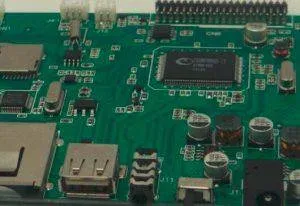
BGA and CSP rework is its own discipline: preheat from below, a controlled profile measured at the part, a reballing fixture and X-ray verification of the result. Re-balling in-house is part of the service for exactly this reason — a returned board with a lifted ball is usually cheaper to reball than to scrap.
The failure mode to watch is the joint that looks right and is not: a ball that did not collapse fully, or a void under the die-side pad, only shows under X-ray.
Heat, moisture and the board itself
Rework heats the laminate as well as the joint. A board that has absorbed moisture can delaminate or blister when the iron or the hot air arrives, so boards that have been stored in a humid environment are baked before rework. Bow and twist limits still apply afterwards — a board that no longer sits flat will not place correctly in the next assembly step.
Records and reinspection
Every repair is recorded and reinspected. Optical inspection for the visible joints, X-ray for the hidden ones, and retest of the affected net at minimum. Workmanship is judged against IPC-A-610, with the first-article baseline from the FAI note as the reference for what the joints looked like before the repair.
The limits that decide pass or fail across the build are described in the inspection note; the process itself is on the assembly services page.