What thin buys
Three things, and only three:
- Height. A 0.4 mm board instead of 1.6 mm frees 1.2 mm in a product where every millimetre counts.
- Weight. Less laminate and less copper per board, which matters in portable and wearable products.
- Thermal path. A thinner dielectric puts the copper planes closer to the components, which can help heat spread in a small package.
It does not buy flexibility. A 0.2 mm FR-4 board bends, but it is not a flex circuit: it will crack at a bend radius that a polyimide flex would survive. Where the board has to move, the right answer is a flex or rigid-flex build, not a thin rigid board.
Handling is the design constraint
At 0.1–0.4 mm the panel is a sheet, not a plate. It sags in the operator's hands, it warps in the oven, and it does not sit flat on a fixture unless something holds it.
The practical consequences:
- Panelisation needs more support than usual — a frame, or rails that stay with the panel through assembly.
- Assembly uses a carrier or vacuum support; the board is not placed directly on the machine table.
- Depanelisation is gentler: V-scoring a thin board leaves very little web, so routing or laser depanelisation is often the better choice.
- Shipping is in a rigid carrier, not a stack.
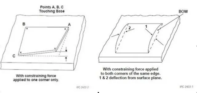
Warpage
Bow and twist are the acceptance measure, at 0.7 % maximum — and thin boards reach that limit easily. Copper balance matters more, not less: an asymmetric stack on a 0.2 mm board warps visibly, while the same imbalance on a 1.6 mm board may stay inside tolerance.
Two controls: keep the lay-up symmetric around the centre line, and avoid large copper-free areas on one side.
Vias, holes and routing
The aspect ratio limit of 15:1 is not the binding constraint at thin gauges; the process and handling are. A 0.15 mm mechanical hole or a 0.1 mm laser microvia is available, and a thin dielectric actually helps the laser drill.
What does change is registration: a flexing panel moves between imaging and drilling, so the drill-to-copper margin is checked rather than assumed, and small annular rings are riskier than they look on paper.
When thin is the wrong answer
If the requirement is "fits in a 3 mm gap", thin FR-4 is right. If the requirement is "bends during use", it is not: a flex circuit or a rigid-flex with a defined bend area is the correct construction, and a thin rigid board used that way will fail at the bend.
The published thickness range and hole limits are on the capability page; the fabrication sequence is in the process note, and the assembly support question in the PCBA manufacturing page.