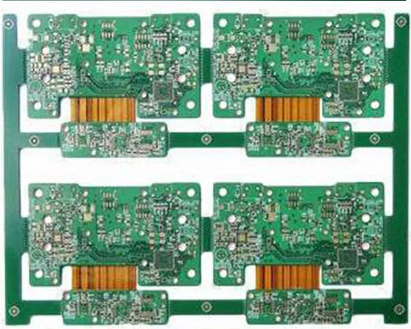
A rigid-flex board splits the work between two materials: the dense, well-supported sections stay on FR-4, and the connection between them is made on polyimide that folds into the shape of the housing. The flex is designed to sit at a fixed deflection — it is formed into its curve during fabrication or assembly, not left to flex through the life of the product.
What the construction removes
- Connectors — the mating connector pair and the flex-to-board interface disappear, so there are fewer parts to buy, stock and place.
- Signal path — transmission becomes rigid board to flex to rigid board instead of rigid board to connector to flex to connector to rigid board. Fewer changes of medium means less attenuation at the interfaces, which helps products that depend on signal accuracy.
- Assembly — fewer components cut SMT and unit-assembly man-hours, and fewer part numbers cut the management and inventory that goes with them.
- Reliability — the joints that fail first in a plug-and-socket connection are not there at all.
How a rigid-flex board is built
The flex core is fabricated first. FR-4 and prepreg are drilled and browned, the lay-up is riveted and pressed in a single cycle — copper-clad laminate, prepreg, the finished flex core, prepreg, top laminate — and the panel is then trimmed and measured for expansion and contraction, because polyimide moves and the registration of every later layer depends on it. Drilling, plasma de-smear, copper deposition and pattern plating follow, then outer-layer imaging, solder mask, finish, electrical test, punching and final inspection.
Design and cost trade-offs
A rigid-flex board costs more than a separate flex plus a rigid board, and the gap can look large before the connectors, the assembly labour and the inventory it removes are counted. A carrier is often needed to hold the flex sections flat through SMT and reflow, which adds assembly cost; bend regions are kept free of plated through-holes, stiffeners are used where a connector has to stay flat, and the layer count, copper weight and stack-up symmetry are set so the panel stays flat after pressing.
Where rigid-flex boards are used
Handheld and smart devices, camera modules, medical equipment such as implantable and monitoring devices where space and weight decide the design, and security and control systems with a display or a sensor on a moving part. Where the circuit bends continuously but does not need a rigid section, a flexible PCB is the simpler answer.
Getting a quotation
Send the Gerber set with the stack-up, the rigid-to-flex ratio, the bend radius and the layer count. Prototypes come back in 1–3 days and medium volume in 4–10 days; the process limits behind the quotation are on the capability page and the issued certificates on the certifications page.
Rigid-flex boards that continue into assembly are covered on the China PCB assembly page, including sourcing and box build.