Start with the bend, then design around it
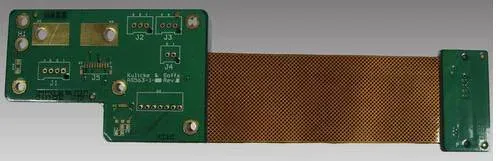
A rigid-flex board is a flex core with rigid sections laminated on either side, so the design has one region that must move and several that must not. The bend radius sets the minimum geometry; everything else is placement discipline around it.
Four rules cause most of the rework.
Rule one: the bend area is a keepout
Nothing that stiffens the flex belongs inside the bend: no plated through holes, no stiffener, no coverlay window, no component, no solder joint. The coverlay and the stiffener edges sit outside the arc with a margin, because adhesive squeezes out during lamination and the edge of a stiffener inside a bend is where a conductor eventually cracks.
The keepout width follows from the radius and the fold angle: the arc length of the bend plus the tooling margin on each side. That number is agreed in DFM and drawn on the fabrication print, not left to the layout tool.
Rule two: conductors cross the bend, never follow it
A conductor that runs along the bend line is loaded along its length; one that crosses at right angles is loaded across its width, which is the direction copper handles far better. Where a signal has to turn inside the flex region, it turns with a radius, not with a corner.
The same logic applies at pad transitions: teardrops and gentle tapers remove the stress concentration that a square shoulder creates.
Rule three: copper sits on the neutral axis
In a bend, the material on the outside of the curve is in tension and the material on the inside is in compression. Copper placed away from the neutral axis — directly opposite another copper layer — is stretched on every cycle, and it cracks first.
The fix is a stack-up decision: keep the flex core symmetric, avoid stacking copper directly opposite copper in the bend, and where a design needs two conductive layers in the tail, accept a lower cycle life or move to a single layer in that region. Copper is available from 0.5 to 2 oz; the flexible section is not the place for the heavier end.
Rule four: the transition is a design feature
Where flex meets rigid, the stiffener or the rigid laminate ends abruptly and the bend starts. That transition carries the highest stress on the part. It is placed away from connectors, given a gradual taper rather than a straight edge, and kept clear of vias.
What to send with the design
The stack-up, the bend location and radius, the fold angle and whether the bend is formed once or moves in service, the stiffener drawing, and the connector footprints with their tail thickness. Those inputs let DFM check the keepout, the copper balance and the panelisation before tooling.
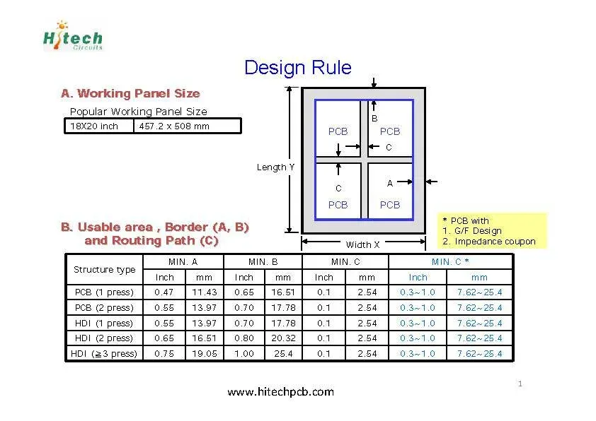
Rigid-flex builds run to 12 layers with 0.002″ line and space and 0.006″ minimum holes on panels up to 9.842″ × 19.685″; the rigid-flex product page lists them with the capability page.