Menu
Blog

Rigid-Flex Stackup Design

A rigid-flex board is a stackup decision before it is a layout. The flex core, the bond plies and the stiffeners set what can bend and how far.

Hitech Circuits Engineering Desk

Shenzhen, China · PCB fabrication and assembly

2 min read

Published:

Last updated:

Technical review: Process figures checked against our published capability sheet. View capability sheet

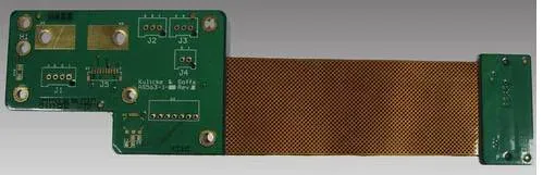
Flex-rigid PCB (Rigid-Flex PCB) design option for PCB layer stackup

The stackup is the design

A rigid-flex build is a flex core sandwiched between rigid sections, bonded with no-flow prepreg. Everything that matters — bend radius, impedance, thickness — follows from how many flex layers you use and where the stiffeners stop.

Options by layer count

  • One flex layer — the simplest and cheapest, suited to a single bend that stays put after assembly.
  • Two flex layers — allows crossing conductors and controlled impedance in the flex tail.
  • Multiple flex layers with rigid sections — up to 12 layers in our build, for assemblies that fold into a housing.

Details that decide yield

  • Keep the copper balanced around the neutral axis of the bend.
  • Route conductors perpendicular to the bend line, never along it.
  • Use teardrops at pad transitions and avoid via holes in the bend region.
  • Specify the stiffener material and thickness where connectors mount.

What we need to quote

Send the layer stack, the bend location and radius, the stiffener drawing and the connector footprints. We laminate rigid-flex up to 12 layers, with 0.075 mm trace and spacing and board thickness from 0.1 mm to 6.0 mm, and we will flag any stackup that cannot survive the stated bend.


Technical Specifications

Rigid-flex layer count
up to 12 layers
Board thickness
0.1–6.0 mm
Minimum trace / spacing
0.075 mm / 0.075 mm

Frequently Asked Questions

  • How is the bend area defined in a rigid-flex stackup?

    By removing the stiffeners and the bond plies in the bend region so only the flex core remains, and by keeping the copper balanced on both sides of that core. The bend radius should be at least ten times the flex thickness for a static bend; dynamic bends need more.

  • Can a rigid-flex board use the same design rules as FR-4?

    The rigid sections can, but the flex section cannot: coverlay replaces solder mask, teardrops and gentle transitions matter more, and vias should be kept out of the bend. Treating the whole board as FR-4 is the most common cause of flex failures.

← Blog

Related engineering notes

Request a customer quote

Free engineering review and quote for PCB manufacturing, PCB assembly, component sourcing and box build.