The comparison is not like for like
A rigid board is a structure. A flex circuit is a moving part. Comparing their reliability without stating the motion is like comparing a bracket with a hinge.
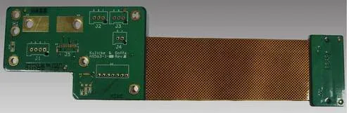
Used as a static bend — formed once during assembly and fixed in place — a flex circuit is extremely reliable: there is no connector to work loose, no wire to fatigue, and the conductor is encapsulated between polyimide and coverlay. The failures that plague cable assemblies at the crimp simply do not exist.
Used as a dynamic hinge, reliability becomes a design number: bend radius, copper thickness, position of the copper relative to the neutral axis, and the number of cycles required.
The four failure modes
- Conductor fatigue. Copper cracks at the outside of a tight bend after repeated flexing. It is a function of strain amplitude, and strain amplitude is set by radius and by how far the copper sits from the neutral axis.
- Coverlay or adhesive delamination. Heat, moisture and flexing together break the bond, usually starting at an edge or a window.
- Barrel cracking. A plated through hole inside a bending region is a rigid tube in a moving film; it cracks at the barrel-to-pad junction.
- Pad lift. A solder joint near a bend concentrates strain at the pad edge until the copper lifts off the film.
None of these is a material defect. Each one is visible in a design review, and each one is cheaper to fix in layout than in a returned lot.
Static and dynamic are different specifications
For a bend formed once, the working rule is a radius of at least ten times the flex thickness, with the copper balanced and no holes in the bend. For a bend that moves in service, that margin is nowhere near enough — the radius grows by roughly an order of magnitude, the copper thins, and the construction may change to a single conductive layer in the flexing zone.
The qualification then follows the application: a bend-cycle test at the radius and stroke the product uses, thermal cycling for the assembly process, and visual and dimensional checks against the acceptance class on the drawing. Rigid boards here are accepted to IPC-6012B and IPC-A-600H; the flexible counterpart is IPC-6013, and the class should be named on the drawing rather than assumed.
What to specify
State whether the bend is static or dynamic, the radius, the fold angle, the cycle count if it moves, and the temperature range. Those five answers decide the stack-up, the copper weight and the test plan — and they are the reason two flex circuits that look identical on a Gerber set can have very different service lives.
Substrate and copper ranges are on the flexible PCB page and the capability page; the layout rules that protect bend life are covered in the flex failure notes.