What size changes
Area affects cost linearly; span affects everything else non-linearly.
- Material and process: more laminate, more copper, larger tanks, larger exposure and etch equipment.
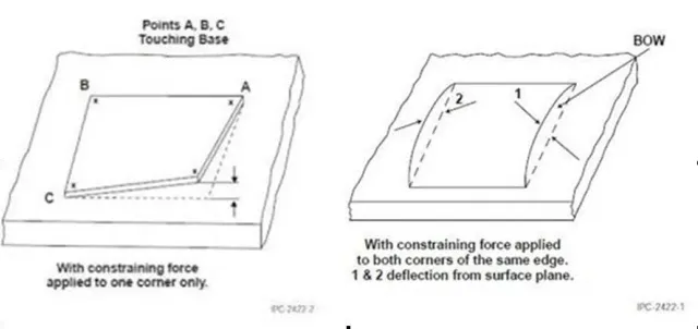
- Flatness: the same 0.7 % limit allows a much larger absolute deflection over 1.9 m than over 200 mm.
- Handling: a large panel is heavy and flexible in the middle, so it needs support at more points.
- Assembly: printer, placer and oven must accept the panel, and the fixture must hold it flat.
Flatness is the main battle
Two boards with the same stack-up can differ entirely in flatness if the copper distribution differs. On a large board the effect is visible before it is measured.
Controls that work:
- Symmetric lay-up. Copper on one side only bends the board during lamination; mirroring the heavy areas around the centre line is the single most effective fix.
- Balanced copper distribution in plan. A large empty area on one corner is a warp waiting to happen; thieving or a ground pour evens it out.
- Thickness margin. A thicker board resists warp, at the cost of weight and drilling.
- Cooling control during lamination. Press cooling cycles matter more on large panels; a rushed cool sets the stress in.
Design rules for long boards
Large boards are often backplanes or panels carrying many connectors, and that changes the routing priorities:
- Length matching across long spans is easier to control, but skew from the laminate matters more: prepreg dielectric constant varies across a large panel.
- Return paths have to be continuous over the whole length; a plane split two-thirds of the way down a backplane is a signal-integrity problem that no amount of length tuning fixes.
- Connector placement is usually fixed by the mechanical design, which pushes the routing problem into the middle of the board where there is more room.
- Impedance is held to ±10 %, but the coupon has to represent the long trace, not just the short test structure.
Assembly and transport
The assembly line needs the panel to fit its conveyor, its printer and its oven, and to be supported so it does not sag. Where the maximum panel is too large for the line, the board is built as a smaller array and assembled in a fixture, or assembled in sections.
Transport is part of the design too: a 1.9 m panel needs a rigid carrier and packaging that does not apply point loads.
When to split the board
A single large board is not always the right answer. Splitting it into two boards joined by a connector, a flex tail or a rigid-flex section can:
- reduce the panel size to something the assembly line handles easily,
- localise thermal expansion and warpage,
- allow a cheaper laminate for the non-critical half,
- make service and replacement possible.
The trade-off is connector cost and signal integrity across the joint — which for a backplane is exactly where the engineering effort goes.
The published limits are on the capability page; the panel rules are in the panelisation note, and the fabrication sequence in the process note.